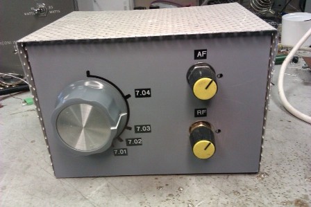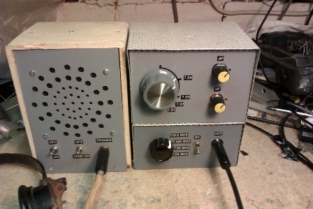

Here is a 40m CW receiver for use with the 40m CW QRP transmitter. Again cheap, easy to obtain components are used throughout the design. Performance is good, signal levels of 3uV at the antenna socket are easily copied and selectivity is excellent due to the use of a 9MHz CW crystal filter ( G-QRP club ). The set also has RF derived AGC although this can be omitted if desired reducing the component count slightly. Local oscillator signal injection is provided by a VXO using a 2MHz ceramic resonator giving a coverage of most of the CW portion of the 40m band. Good quality VFO's can sometimes be difficult to acheive for those not experienced in building these, so a VXO is used here. The performance of the VXO very good, after ten minutes " warm up " it is absolutely solid, no tuning adjustments need be made for half an hour or so, I was pleasantly surprised by this considering a cheap polycon tuning capacitor is used.
The antenna signal enters the set via a 9MHz trap and a two pole bandpass filter L1, L2 feeding Tr1, a FET grounded gate RF preamp.The FET preamp is used to overcome the insertion loss of the mixer and crystal filter. Initialy a common source pre amp was used but this was prone to strong broadcast signal break through, although it did produce slightly more gain. The drain load for Tr1 is T1 which along with D1, D2 form a single balanced mixer.
Local oscillator from the VXO is injected at the center tap of T1. From here the mixing products pass through T2, a 9:1 impedance ratio transformer in order to provide a good match to the 50 Ohm impedance crystal filter. The wanted IF signal leaves the crystal filter via a 1:9 step up transformer, this provides a good match to following cascode IF amplifier. Two cascode IF amplifiers are used giving a gain of roughly 70dB in total. The IF transformers used are standard 10.7 MHz interstage IFT's with an additional 10pF connected across the primary. The second IF amp feeds a diode product dectector D3, D4. and also feeds the AGC amplifier.
A crystal oscillator, Tr8, is used as a BFO for carrier re-insertion at the product detector. A 9.0015 MHz or 9.000 Mhz xtal is used here as the CW filter has a center frequency of 9.0008 MHz, this is probably so a 9.0015 MHz USB Xtal could be used for carrier reinsertion in the set it was intended to be used in thus saving the cost of a seperate CW carrier Xtal. ( several of these filters were sweep tested and they all had a center frequency of 9.0008 MHz ). Recovered audio from the detector passes to common emitter preamp Tr9 via the volume control and then to the audio power amp. A LM386 can be used here ( you will still need the preamp Tr9 ) if you wish, indeed it is probably cheaper to do so. I used the discrete audio amp as a design exercise and to keep the set " chip free ".
The circuit for the VXO is straight forward. A colpits variable oscillator is used. A zener diode is used to stabilise the DC supply to VXO Tr6. A buffer Tr7 follows the oscillator which reduces oscillator loading and pulling by the mixer. A cheap polycon variable capacitor ( G-QRP ) is used for the tuning control, no reduction gearing is required - tuning is smooth and easy providing a large control knob is used. Approximatley 40 kHz of swing is given by this VXO, resulting in a band coverage of 7.00 MHz to 7.045 Mhz thus matching the range of crystals used in the transmitter. Experimentation with the feedback capacitors in the VXO may give a greater tuning range. Polystyrene feedback capacitors are to be recommended for use in the VXO, I used a mixture of polystyrene and ceramic disc as I did not have correct values available. If you are an experienced VFO builder then you could build a VFO giving coverage of the whole of the 40m band if desired.
RF derived AGC is used in this set. A small proportion of the IF signal is taped off from Tr5 collector via C1 a 3.3pF capacitor to feed a emitter follower buffer Tr10, therefore very little loadind is presented to Tr5 collector. A low gain preamplifier Tr11 follows the buffer via the AGC threshold control P1. Tr11 collector load R7 feeds a rectifier / voltage doubler D1, D2. The result is a DC voltage proportional to the received signal strength present at the cathode of D2. This is used to control Tr12, the stronger the received signal the harder Tr12 conducts thereby reducing the the voltage on the AGC control line. During TX the AGC voltage is grounded by Tr13 allowing P2 control of the IF gain for correct sidetone level. It is important to keep any BFO signal out of the IF amplifier ( apart from the IFT2 ) as this will upset the AGC action, screening should be used between the BFO and IF amp. The main purpose of this AGC circuit is to stop strong stations from deafening you when the IF gain control is at maximum. If you do not require AGC then it is a simple matter to use a pot as a manual gain control, details are shown for this in the AGC amp circuit diagram. No side tone oscillator is required as the receiver will pick up the TX due to proximatey, P2 is adjusted for a suitable sidetone level whilst holding the key down.
Barry Zarucki M0DGQ
HOME